| Target shaft footprint |
1.0–1.5 m² |
Approximately 1,000 × 1,000 mm to 1,200 × 1,250 mm |
Place beside a stair, at the end of a corridor, or within a planned service core to reduce visual impact. |
Confirm whether the stated dimensions refer to the clear internal shaft, structural opening, or finished external enclosure. |
| Recommended early-stage shaft module |
About 1,100 × 1,100 mm |
Approximate footprint: 1.21 m² |
Works well as a square architectural “core” that can be aligned with wall panels, cabinetry, or a stair balustrade. |
Actual dimensions depend on cabin size, door configuration, guide rails, counterweight arrangement, and equipment layout. |
| Small residential cabin |
Approximately 700–900 mm wide × 900–1,100 mm deep |
Common compact planning envelope; not a universal standard |
Suitable for one person or limited household movement where local regulations permit. |
Usable cabin area is smaller than the shaft footprint because the shaft contains structural and mechanical components. |
| Typical compact rated load |
Approximately 250–450 kg |
Capacity is selected according to cabin size, travel, use pattern, and applicable regulations |
Use a lighter visual language—glass, timber slats, or painted panels—without treating decorative finishes as structural elements. |
Rated load must be established by the elevator designer and certified according to the applicable jurisdiction. |
| Door clear opening |
Approximately 600–800 mm |
Wider openings generally require more shaft width and landing space |
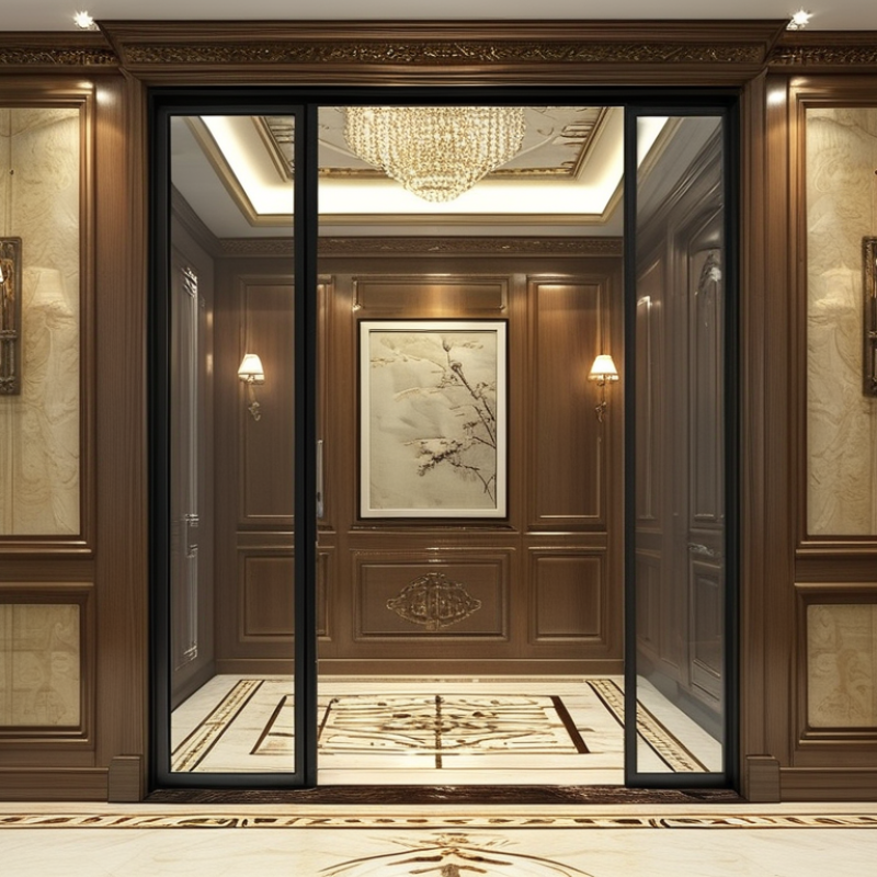
Conceal the door with a flush wall panel, matching veneer, or a full-height architectural door treatment. |
Door width, landing clearance, fire rating, and accessibility requirements vary by location and building type. |
| Landing circulation zone |
Preferably 1,200–1,500 mm clear in front of the door |
Allow additional space where wheelchair turning or two-way traffic is expected |
Keep the landing free from consoles, planters, shoe cabinets, and door swings that could obstruct access. |
Use the local accessibility code for the required maneuvering and turning dimensions. |
| Minimum corridor relationship |
Keep at least one direct, unobstructed approach |
Avoid placing the landing directly at a stair nose or in a narrow pinch point |
Use a short recessed lobby, change of floor finish, or ceiling detail to make the elevator feel intentional rather than hidden accidentally. |
Maintain required headroom, guarding, handrail, and escape-route clearances around adjacent stairs. |
| Structural coordination |
Reserve a continuous vertical zone through all served floors |
Coordinate slab openings, beams, columns, foundations, and lateral bracing before construction |
Align the shaft with existing structural grids, wet walls, storage walls, or a stair enclosure to minimize visual and construction disruption. |
A structural engineer must verify loads, openings, vibration, shaft stability, and any pit or foundation requirements. |
| Overhead and pit planning |
Reserve space above the top landing and below the lowest landing |
Exact values vary significantly by elevator system and code; do not assume zero pit or zero overhead |
Use a ceiling bulkhead, roof-level equipment zone, or service cupboard only after the required clearances are confirmed. |
Some systems may reduce pit or overhead requirements, but this must be documented by the elevator designer and approved locally. |
| Machine-room strategy |
Prefer a system designed for the available equipment arrangement |
Machine-room-less layouts can reduce a separate room but still require service access |
Place access panels inside a utility closet, wardrobe zone, or coordinated ceiling hatch rather than behind permanent finishes. |
Maintenance access, ventilation, electrical isolation, and safe rescue procedures must remain available at all times. |
| Fire and smoke separation |
Treat the shaft as a protected vertical opening where required |
Fire resistance, door rating, smoke control, and lobby requirements depend on local code |
Use rated wall assemblies with compatible finishes; avoid concealing required signage, detectors, or protected door hardware. |
Decorative cladding must not compromise the tested fire performance of the shaft or landing doors. |
| Acoustic control |
Separate the shaft from bedrooms where possible |
Use a buffer zone such as storage, bathroom, stair, or corridor wall |
Place wardrobes or built-in cabinetry on the bedroom-facing side to create a visual and acoustic buffer. |
Noise depends on drive type, guide system, structure, installation quality, and operating speed; request project-specific acoustic data. |
| Visual concealment method |
Make the landing door part of the wall composition |
Flush panels, matching paint, timber veneer, microcement, or aligned wall battens |
Continue vertical joints, skirting lines, lighting tracks, and material proportions across the door where permitted. |
Do not block door movement, emergency release points, inspection access, ventilation, or mandatory identification. |
| Lighting approach |
Use indirect or evenly distributed lighting |
Linear wall washers and ceiling coves are generally less visually intrusive than a single bright downlight |
Integrate lighting with the landing threshold and corridor rhythm so the elevator is legible without becoming a focal object. |
Lighting must not cause glare, obscure controls, or interfere with safety signage and emergency lighting. |
| Wet-area separation |
Avoid placing plumbing directly against the shaft unless engineered |
Maintain waterproofing, drainage, and inspection access around any adjacent bathroom or kitchen |
Use a dry storage or circulation buffer between the elevator enclosure and wet rooms when the plan allows. |
Water ingress can damage equipment and finishes; coordinate waterproofing and drainage with the structural and elevator teams. |
| Finishing allowance |
Reserve additional build-up beyond the clear shaft |
Allow for wall lining, fire-rated board, acoustic layers, door frames, skirting, and service access |
Set the final wall grid from the finished face, not only from the structural opening. |
Early drawings should distinguish clear dimensions, structural dimensions, and finished dimensions. |
| Best locations in a compact home |
Stair core, corridor end, entry vestibule, or stacked service zone |
Choose a location that minimizes new circulation and serves all required floors efficiently |
At an entry, disguise the elevator as a tall storage wall; beside stairs, align it with the balustrade or handrail geometry. |
Check travel distance, landing access, evacuation strategy, daylight, privacy, and maintenance access before finalizing the position. |
| Design approval checkpoint |
Freeze the shaft after coordinated technical review |
Review architecture, structure, electrical, fire safety, accessibility, and maintenance requirements together |
Issue a coordinated reflected ceiling plan, finish schedule, door elevation, and service-access diagram. |
 Dave Lift